
Low voltage electrical installations

CYPELEC Core is a free application for the calculation of low voltage electrical installations that incorporates the CYPELEC REBT calculation engine. CYPELEC Core allows users to draw single-line diagrams of the installation and configure the features of the composing elements.
The calculation checks performed in the application are based upon the specifications from the international IEC regulations.
CYPELEC Core is integrated into the Open BIM workflow via the BIMserver.center platform.
Working with BIMserver.center
Users must register on the BIMserver.center web platform to be able to use the application. Once the application and BIMserver.center® synchronizer have been downloaded and installed, the new projects created by the user must have an associated project stored on the platform, thus allowing an Open BIM collaborative workflow.
CYPELEC Core is free and available for download on the BIMserver.center platform.
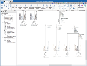
User interface
An accessible user interface with multiple editing aids –preconfigured switchboards, groups of lines, predefined circuits, copy, paste, move and match properties; undo-redo and new installation components (capacitor banks, LV/LV transformers, etc.)
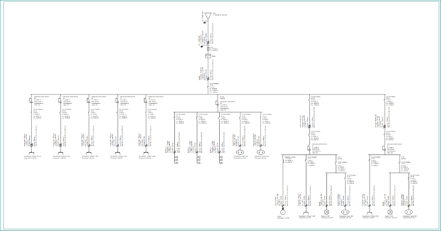
Design
CYPELEC Core has an automatic line design system that allows users to configure the criteria that they want the application to take into account during this process.
The design can be changed in the dialogue box "Design options". This can be accessed by selecting the ![]() button in the toolbar, which is situated on the single line tab or tree tab (“project” group). In this dialogue box you can:
button in the toolbar, which is situated on the single line tab or tree tab (“project” group). In this dialogue box you can:
- Increase the cable section to comply with the nominal current or rated current of the limiting factors from the installation.
In this option you must specify the maximum number of section increments that you require the program to automatically carry out. - Design the maximum admissible voltage drop, with the added possibility of enabling in the design a voltage drop compensation between the interior installation and the individual branch circuit. In this option you must specify the maximum number of section increments that you require the program to automatically carry out.
- Design protective devices against overloads, with the added possibility of adjusting the protective nominal current to the maximum current-carrying capacity of the cable.
- Design protective devices against short-circuits of ultimate breaking capacity and service breaking capacity.
- Design the calibre of protective devices against indirect contacts.
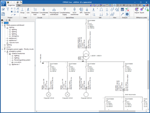
Systems
There is great versatility when it comes to planning the systems, in terms of the number of elements, multi-level nesting and types of load.
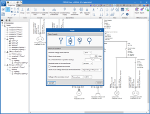
Types of Supply
Different types of supply: low voltage network, single generator set and electrical substation.
As well as specifying the main type of supply, the application offers the possibility to insert a complementary supply, among those indicated, through a generator set that can serve the whole installation, a part of it or to turn on the emergency services that are deemed necessary in case the normal supply fails.
Electrical equipment
In CYPELEC Core the following devices can be placed in the electrical installation:
- LV/LV Transformer
There is the possibility to introduce a transformer along the installation to increase or decrease the nominal voltage. Such is the case with the use of a transformer for installations powered by safety extra low voltage (SELV).
- Capacitor bank
The power factor in any part of the installation can be improved by adding a capacitor bank. It can be installed either individually (receiver) or collectively (a group of circuits).
- Motor
CYPELEC Core checks the motor starting current and allows starters to be used to reduce the starting current, and in this way, limit its impact on the installation. It also takes into account the contribution of asynchronous motors on short-circuit currents. For more information, go to the following sections:
Checking of the motor starting current and the use of starters
At the moment of start up, the asynchronous motors require higher voltage levels than what they would usually need in nominal operating conditions. These over currents can generate very marked voltage drops in the installation. This is why different electrical regulations limit the relation between the starting current and the nominal current, according to the power of the motor in question.
The application allows the starter data to be set up by manually introducing a nominal current multiplier coefficient. Alternatively, the American nomenclature established by the NEMA code can also be used, which appears in the technical specifications of some motors.
Users can select a starter to reduce the starting current, and in this way limit its effect on the installation. The types of starter that users can choose are:
- Direct-on-line starter
- Star-delta starter
- Autotransformer starting (2 start points)
- Autotransformer starting (3 start points)
- Rotor/stator-resistance starter
- Variable frequency drive
The selected starter, as well as affecting the calculation, is also reflected in the single-line tab with its corresponding icon.
Contribution of asynchronous motors to short-circuit currents
Due to the inertia of the motors in the moment that the short-circuit is generated, each one of them temporarily converts into a power generation source that contributes to increasing the value of the maximum short-circuit current. For this reason, and following IEC 60909, this circumstance has been implemented so that the short-circuit current’s real value is taken into account in each one of the installation lines.
Calculation accuracy
Precise calculations by using the symmetrical components method to obtain short-circuit currents according to IEC 60909, or calculation of unbalanced three-phase systems.
Short-circuit calculation through the symmetrical components method
CYPELEC Core carries out the calculation of short-circuit currents following the symmetrical components method. Based on Thevenin’s theorem, and is applicable to all types of network up to 230kV, it consists of the induction of a source of equivalent tension into the point of the short-circuit, and the substitution of each fault loop element by its corresponding positive, negative and zero sequence impedances. Once this system has been established, the short-circuit current is obtained at the same point in which the “virtual” source of tension was placed.
Thanks to its outstanding analytical aspect and its greater precision compared to other procedures, it has the best tools available with regards to the calculation of defects in the installation.
Hypothesis for the calculation of short-circuit currents
The maximum and minimum short-circuit currents are checked in each one of the established supply scenarios, in the case that more than one exists, so that the protective devices guarantee protection against short-circuits for all the power supply units.
Calculation of currents in unbalanced phases
When planning a three-phase electrical installation it is usually assumed that the distribution of the loads in each one of the stages will be achieved in a balanced way. This way of proceeding may be more convenient when it comes to considering the design, but it is only a mere approximation, due to the fact that the overall balance is very difficult to achieve. The possibility of designing the installation with an unbalanced phase distribution allows users to select the phase to which they will connect each one of the loads. In this way, it is possible to carry out a preliminary study on the distribution of the loads, and thus avoid unbalances between the phases that can affect the installation’s correct functioning.
Furthermore, in the case that the planned installation presents some type of unbalance between the phases, the application will carry out all the corresponding checks so that the line’s real behaviour is modelled. In this sense, the currents circulating through each one of the phases and through the neutral are taken into account to compensate for the unbalance between them. These currents will be considered when correctly designing the section of each conductor (including the neutral), and both the simple voltage drops (phase-neutral) and the accumulated voltage drops (phase-phase) will be calculated.
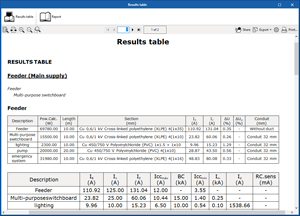
Justification report
Justification report of all the checks carried out by the application.

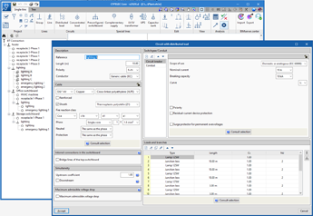
Distributed loads and Preconfigured switchboards
With any type of configuration it is possible to introduce predefined elements, distributed loads and preconfigured switchboards. The power of these tools lies in the fact that users can store the types of loads and distributions that they use the most. This way, they can be used as many times as needed without having to configure each one separately again.
- Distributed loads
The concept of distributed loads is applied to situations in which users want to introduce groups of loads with a set configuration, so that they are treated as a block within a group. For example, in the case of an installation featuring large dimensions, like an industrial ship or a hospital, where light will be distributed by sectors. Consequently, it is more convenient to introduce a distributed load block and copy it multiple times, then make small modifications to each one of them.
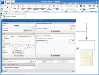
- Preconfigured switchboards
The application method will be similar to distributed loads, but with the exception that modifications made in a block will be reflected in all of the same types of block. A clear example of this would be the design of a group of houses, for which the distribution of the electrical lines is previously determined, and then as many blocks as houses required are inserted.
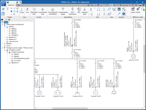
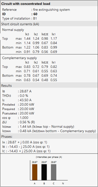
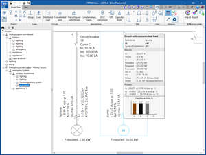
Displaying of calculated magnitudes
Direct display of the calculated magnitudes on the diagram itself, with drop-down “tooltips”.
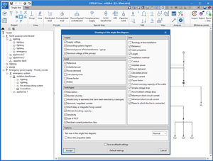
Plans
Generation of plans with detailed information about the lines and loads. The application allows users to create a selection of parameters in order to display them in the single-line diagrams. By clicking on the button ![]() "Drawings of the single-line diagram", a window will open in which you can carry out the previously mentioned selection.
"Drawings of the single-line diagram", a window will open in which you can carry out the previously mentioned selection.
Tel. USA (+1) 202 569 8902 // UK (+44) 20 3608 1448 // Spain (+34) 965 922 550 - Fax (+34) 965 124 950